2D-setup manual
by : Jan Hidding (june 2018)
original file in pdf format
Turn on system
- Interlock on
- Turn on laptop hurricane (com port: 2)
- Turn on SDG-II (backside)
- Turn on oscilloscope
- Big chiller
- Amplifier (knob then key)
- Fan (under table)
- Dazzler (backside)
- Laptop dazzler
- Power supply for diodes
- Lockins
- Turn on PC
- Spectra-Physics box: Wait until “TEMP” stops blinking. Then Laser on/off (keep pressed until laser starts)
- Laptop hurricane: ON/OFF (keep pressed for few seconds, wait for laser to warm up)
- Laptop hurricane: Shutter (keep pressed until red box lights up)
- After warming up is complete: ON/OFF (keep pressed until “Emission”)
- Wait for power to ramp up (“pulsing” indicator should go on)
- Reset on SDG-II
- Wait for hour to let laser warm up
Align everything to increase output power and get peak position of spectrum at 590 nm (16950 cm-1)
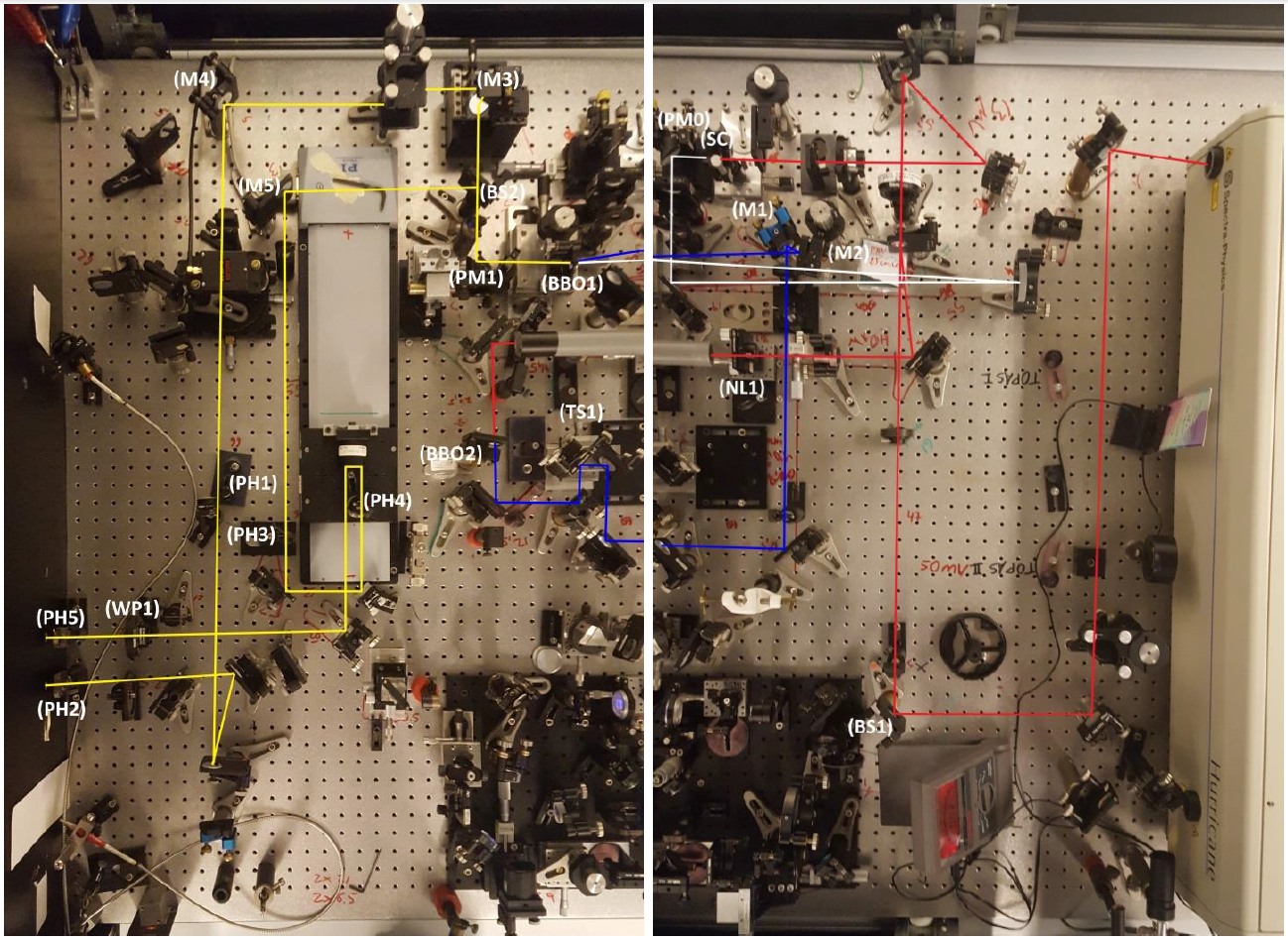
- Use beam splitter BS1 to align beam in to NOPA. Look at spectrum from OCEAN to see if signal is increasing in power
- To improve temporal overlap of blue and white light in BBO crystal, change translation stage TS1. SENSITIVE! Translation stage can be used to get peak position at 590/595 nm
- Improve spatial overlap of the two beams by changing the direction of blue light with M2 or M3
- Align white light ONLY slightly with PM0 into BBO crystal
- If profile of white light is off (spatially chirped), change the knobs of the sapphire crystal (SC) to improve the white light beam profile
- Changing upper knob of BBO crystal (creating broad spectrum) may also improve signal
- Changing 2nd harmonic creating BBO crystal (BBO2) may also improve signal slightly
- Power can be increase with focus of negative lens (NL1) in the telescope configuration. This will deteriorate beam profile (good profile is more important than higher power)
- If beam profile is off, try changing sapphire crystal slightly to get a round homogenous spot
Align probe and pump through pinholes and into spectrometer
- If everything is aligned, one should be able to align probe and pump through pinholes PH2 and PH5 with the parabolic mirror PM1. If not, probe has priority
- Pump is aligned through PH1 & PH2 using M3 and M4 respectively
- Probe is aligned through PH3, PH4, PH5 & PH6 using BS2 and M5. Good alignment with PH4 is important as delay stage needs to be well aligned. Another removable pinhole PH6 should be used on the other side of the board to align probe in to spectrometer
Alignment after board into spectrometer
- To see spectrum on PC: “Extras” -> “Show continuous”
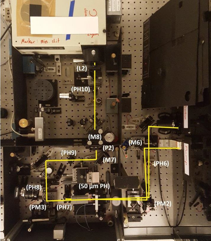
- Check whether probe goes through PH7/8/9/10 and in to spectrometer (without cuvette and pinhole intensity on PC should be around 0.3)
- When misaligned, slightly change PM2 to get in through PH7 and PH8 and PM3 to get it through PH9
- Use M7 and M8 to align through PH10 and increase signal strength. Also use these mirrors to remove any strange fringes in the spectrum
- Lastly change the lens L2 to increase signal
Align pump and probe through 50 μm pinhole
- Block pump beam and align 50 μm pinhole with probe beam (Therefore, only use the stages that translate the pinhole orthogonal to the beam. Do not change the focus position.)
- Block probe beam and align pump beam into pinhole using M6
- Make sure that PH7 is blocking pump and not probe pulse
- Install cuvette and align with pinhole. Use level to position cuvette horizontally
- Block pump and get back reflection of probe on to pump to get a small angle relative to probe
- Clear and measure baselines
- Dim lights and block probe and pump
- “Extra” -> ”Clear baselines”
- “Extra" -> ”Measure baselines” (10000 pulses)
Pump probe to determine time zero (t0) and check if everything is in order
- Set power pump & probe to 200nW (dim roomlight!, take pulse repetition rate into account to set the proper pulse energy, because ΔE=Pavg/f)
- 500Hz 100nW
- 1000Hz 200nW - Use dazzler to chop the pump pulse (fpump=500 Hz, fprobe=1000 Hz) by putting dazzler to A/B mode -> “Load”
- Check if polarization of probe and flow direction are correct
- PC: “Scan” “Select input” -> check:
“VisArray…1.ClockedInput1D_1” & “VisArray…1.ClockedPumpProbeInput1D_1” - Roughly determine t0 by scanning large range with large step size “Scan” -> "Scan"
- Scan motor: PIDelay_1
- Start position: -5000 fs
- End position: 5000 fso Delta position: 20 fs (better use 20 fs here. Otherwise your time zero is ±200fs) - Obtain t0 by fitting integrated signal with XYY
- Move stage to t0: “Motors” -> “Move motor(s)…” -> PIDelay_1=t0
- “Scan” -> “Multi-delta scan…”
- Scan Motor: PIDelay_1
- Delay#1 : 1, NrAverages: 10, Make bidirectional scan
- Start -1000 (delta 200), -200 (delta 20), 1000 (delta 100), 5000 (delta 200), End 30000
2D measurement
- Put Dazzler back to A mode and to “zero”
- Check power of pump and probe (to be sure)
- PC: 2DFT Dazzler -> Settings:
- Nr averages=250
- Max delay (fs)=300/400
- Delta delay=0.6
- Nr Phase states=2 : Multiplier phase 1=1, Multiplier phase 2=-1
- Save single scans: None
- Mark “Crop the X-axis to the spectrum” - To determine whether there is a lot of scattering from the pump, one can block the probe and run a short scan to see whether there is diagonal signal due to scattering:
- 2DFT -> Scan - For real measurement: 2DFT -> Dual loop scan -> Single loop:
- Start position: 0 fs
- End position: 1000 fs
- Delta: 100 fs